


地科岩石礦物偏光用配件
地科岩石礦物偏光用配件
如有需要,請洽業務人員
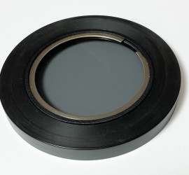
With just a few additional components you can use the NIGHTSEA SFA system to add a polarization viewing capability to stereo microscopes that do not include this. For most polarization applications you need two main elements – polarized light transmitted through the sample, and a crossed polarizer, called the analyzer, above the sample. Many microscopes have an illuminated polarizing stage, but for those that do not you can use the modular Dino-Lite Model BL-ZW1 Polarized Back-Light Stage, available from EMS. To provide the Analyzer, NIGHTSEA offers a high quality glass linear polarizer mounted in the same ring that normally holds our fluorescence barrier filters, so that
it attaches to our adapter ring magnetically.
 |
 |
|
Polarization analyzer add-on |
Dino-Lite polarizing back-light stage |
The images below show a concrete thin section that was originally prepared for fluorescence examination. From left to right we see the sample viewed with transmitted light (polarizer only), with crossed (90°) polarizers, and with the analyzer manually rotated approximately 30°.
The change that can be seen with this last rotation can aid in distinguishing features of interest.
 |
 |
 |
| Concrete thin section, polarizer only | Concrete thin section, polarizer + analyzer |
Concrete thin section, analyzer rotated |
If you do not own the NIGHTSEA SFA system but are still interested in this approach to adding polarization to a stereo microscope you would also need the adapter ring for
the microscope.
 SFA-AD Adapter Ring
The images below are additional examples of polarization viewing with the system.
 |
 |
 |
 |
| LED molded lens, polarizer only | LED molded lens, polarizer + analyzer | Cat claw, polarizer only |
Cat claw, |
Hot tip – add a full wave plate at very low cost!
For some applications it can be valuable to add a full wave retardation plate (also called a first order red plate, lambda (λ) plate, gypsum plate, selenite plate, sensitive violet, or color tint plate) in the optical path. This component can be used to determine the optical sign (positive or negative) of a birefringent specimen and also to enhance contrast in weakly birefringent specimens. The full wave plate is generally positioned above the sample and below the analyzer, but we have found that it works the same positioned above the polarizer and below the sample.
The photos below show (from left to right) a concrete thin section imaged with:
- polarizer only
- crossed polarizers
- crossed polarizers, lambda film above the sample
- crossed polarizers, lambda film below the sample
 |
 |
 |
 |
| polarizer only | crossed polarizers | crossed polarizers, lambda film above sample |
crossed polarizers, lambda film below sample |